| |
|
|
|
|
|
|
|
|
|
|
|
|
|
|
| |
|
Discussion
and References
|
| |
|
Information about
Reinforcement of Welded Branch Connections:
|
| |
|
ASME B31.3 Process
Piping, para. 304.3.3
|
|
|
|
|
|
|
|
|
|
|
|
|
|
|
|
| |
|
Tables and Standards
|
| |
-
|
Table A-1 Basic Allowable Stresses in
Tension for Metals
|
| |
-
|
Table A-1M
Basic Allowable Stresses in Tension for Metals (Metric)
|
| |
-
|
Table A-1B Basic Quality Factors for
Longitudinal Weld Joints in Pipes and Tubes, Ej
|
| |
-
|
Table 304.1.1 Values of Coefficient Y for t
< D/6
|
| |
-
|
Table 302.3.5 Weld Joint Strength Reduction
Factor, W
|
| |
-
|
ASME B36.10M-Welded and Seamless Wrought
Steel Pipe
|
| |
-
|
ASME B36.19M-Stainless Steel Pipe
|
| |
-
|
Mill Tolerance = 12.5%
|
| |
|
|
|
|
|
|
|
|
|
|
|
|
|
|
| |
|
Equations
for Wall thickness calculation of straight pipes under internal pressure
(304.1):
|
| |
|
|
| |
|
For t < D/6, the thickness should be calculated by the
equation:
|
| |
|
|
|
|
|
|
|
|
|
|
|
|
|
|
| |
|
Select T̅ from
ASME B36.10M or B36.19M
|
| |
|
Mill
Tolerance = 12.5%. (See ASTM Standards & appendix S of ASME B31.3)
|
| |
|
T = T̅ (1.00-0.125) = T̅ (0.875) Minimum
thickness required, considering a mill tolerance of 12.5%
|
| |
|
Thickness for design pressure
|
|
|
|
|
|
|
|
|
|
|
|
|
|
|
|
|
|
|
|
|
|
|
| |
|
t =
|
PD
|
|
|
|
|
|
(eq. 3a as per par. 304.1.2)
|
|
|
|
| |
|
2(SEW + PY)
|
|
|
|
|
|
|
|
|
|
|
|
|
|
|
|
|
|
|
|
|
|
|
|
| |
|
The
parameters in the wall thickness calculation of straight pipes under internal
pressure
|
| |
|
equations
above are:
|
|
|
|
|
|
|
|
|
|
| |
|
T̅ = Nominal pipe wall
thickness, inches (mm) from ASME
B36.10M or B36.19M
|
|
|
| |
|
T = Minimum thickness considering a mill tolerance of 12.5%,
inches (mm)
|
| |
|
tm = Minimum thickness required,
inches (mm)
|
| |
|
t = Thickness for design pressure,
inches (mm)
|
| |
|
c = Sum of allowance for corrosion, erosion, slots and threads,
inches (mm)
|
| |
|
P = Internal design pressure, psig (barg) (1bar = 100 kN/m2)
|
|
|
D = External diameter, inches (mm)
|
| |
|
E = Quality factor (table A-1B) of ASME B31.3
|
| |
|
S = Allowable stress at the design temperature, psi (Mpa)
(table A-1 or A-1M) of ASME B.31.3.
|
| |
|
Y = Coefficient that depends on the material and design
temperature (table 304.1.1) of ASME B31.3.
|
| |
|
W = Stress reduction factor of welded joint, paragraph
302.3.5(e) and table 302.3.5 of ASME B31.3
|
| |
|
|
|
|
|
|
|
|
|
|
|
|
|
|
| |
|
The formulas below is used in the pressure design of branch
connections. It is illustrated in Fig. 304.3.3, which does
|
| |
|
not indicate details for construction or welding. Some of the
terms defined in Appendix J are subject to further
|
| |
|
definitions or variations, as follows:
|
|
|
|
| |
|
b = subscript referring to branch & h = subscript referring to run or
header
|
| |
|
d1 = effective length
removed from pipe at branch.
|
| |
|
For branch intersections where the branch opening is a
projection of the branch pipe inside diameter (e.g., pipe-to-pipe fabricated
branch),
|
|
|
|
|
|
|
|
|
|
|
|
|
|
|
|
| |
|
d₁ =[Db ̶
2(Tb
̶ c)]/sin β
|
|
|
|
|
|
|
|
|
|
|
|
|
|
|
|
|
|
|
|
|
|
| |
|
d2 = “half width” of reinforcement zone
|
|
|
|
|
|
|
|
|
|
|
|
|
|
|
|
| |
|
d₂ = d₁ or (Tb ̶
c) + (Th
̶ c)+
|
d₁
|
|
|
|
|
|
| |
|
2
|
|
|
|
|
|
|
|
|
|
|
|
|
|
|
|
|
|
|
|
|
| |
|
L4 = height of
reinforcement zone outside of run pipe
|
|
|
|
|
|
|
|
|
|
|
|
|
|
|
|
| |
|
L₄ = 2.5(Th ̶ c) or 2.5(Tb
̶ c)+Tr
|
|
, whichever is less
|
|
|
|
|
|
|
|
|
|
|
|
|
|
|
|
|
|
|
| |
|
Tb = branch pipe thickness (measured or minimum in accordance
with the purchase specification) except for branch connection fittings (see
para. 300.2). For such connections the value of Tb for use in calculating L4, d2,
and A3 is the
thickness of the reinforcing barrel (minimum per purchase specification),
provided that the barrel thickness is uniform (see Fig. K328.5.4) and extends
at least to the L4
limit (see Fig. 304.3.3.)
|
| |
|
Tr = minimum thickness of reinforcing ring or saddle made from
pipe (use nominal thickness if made from plate)
|
| |
|
= 0, if there is no
reinforcing ring or saddle
|
| |
|
t = pressure design thickness of
pipe, accordingto the appropriate wall thickness equation or procedure in
para. 304.1. For welded pipe, when the branch does not intersect the
longitudinal weld of the run, the basic allowable stress, S, for the pipe may
be used in determining th for the purpose of reinforcement calculation only. When the
branch does intersect the longitudinal weld of the run, the product SEW (of
the stress value, S; the appropriate weld joint quality factor, Ej, from
Table A-1B; and theweld joint strength reduction factor, W; see para.
302.3.5) for the run pipe shall be used in the calculation. The product SEW
of the branch shall be used in calculating tb.
|
| |
|
β = smaller angle between axes of branch and run.
|
| |
|
Required Reinforcement Area. The reinforcement area, A1, required for a branch connection under internal pressure is:
|
|
|
|
|
|
|
|
|
|
|
|
|
|
|
|
| |
|
A₁ =th d₁ (2 ̶ sin β)
|
|
|
|
|
(6)
|
|
|
|
|
|
|
|
|
|
|
|
|
|
|
|
|
|
| |
|
For a branch connection under external pressure, area A1 is
one-half the area calculated by eq. (6), using as th the thickness required
for external pressure.
|
| |
|
Available Area. The area available for reinforcement is defined
as
|
|
|
|
|
|
|
|
|
|
|
|
|
|
|
|
| |
|
A₂ +A₃ + A₄ ≥ A₁
|
|
|
|
|
|
(6a)
|
|
|
|
|
|
|
|
|
|
|
|
|
|
|
|
|
|
| |
|
These areas are all within the reinforcement zone and are
further defined below.
|
| |
|
I.Area A2 is the area resulting from excess thickness in the run pipe
wall
|
|
|
|
|
|
|
|
|
|
|
|
|
|
|
|
| |
|
A₂ = (2d₂ ̶ d₁)(Th ̶ th ̶ c)
|
|
|
|
(7)
|
|
|
|
|
|
|
|
|
|
|
|
|
|
|
|
|
|
| |
|
II.Area A3 is the area resulting
from excess thickness in the branch pipe wall
|
|
|
|
|
|
|
|
|
|
|
|
|
|
|
|
| |
|
A₃ = 2L₄(Tb ̶ tb
̶ c)]/sin β
|
|
|
|
(8)
|
|
|
|
|
|
|
|
|
|
|
|
|
|
|
|
|
|
| |
|
If the allowable stress for the branch pipe wall is less than
that for the run pipe, its calculated area must be reduced in the ratio of
allowable stress values of the branch to the run in determining its
contributions to area A3.
|
| |
|
III.Area A4 is the area of other
metal provided by welds and properly attached reinforcement. [See para.
304.3.3(f).] Weld areas shall be based on the minimum dimensions specified in
para. 328.5.4, except that larger dimensions may be used if the welder has
been specifically instructed to make the welds to those dimensions.
|
| |
|
In ring
|
|
|
|
|
|
|
|
| |
|
A₄ = (Tr)(Dr -
|
Db
|
)
|
|
|
|
|
|
|
|
| |
|
sin β
|
|
|
|
|
|
|
|
| |
|
In fillet welds
|
|
|
|
|
|
|
|
| |
|
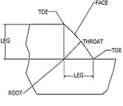
Considering all
fillet welds are equivalent to 45 deg fillet welds
|
|
|
|
|
|
|
|
|
|
|
|
|
|
|
|
|
|
|
| |
|
A₄ = No. Fillet welds x Aby fillet weld
|
|
|
|
|
|
|
| |
|
|
|
|
|
|
|
|
|
|
|
|
|
|
| |
|
A₄ =
4 x 1/2 x Leg²
|
|
|
|
|
|
|
|
|
|
|
|
|
|
|
|
|
|
|
|
|
|
|
|
| |
|
Reinforcement Zone. The reinforcement zone is a parallelogram whose length
extends a distance, d2, on each side of the centerline of the branch pipe and whose
width starts at the inside surface of the run pipe (in its corroded
condition) and extends beyond the outside surface of the run pipe a
perpendicular distance, L4.
|
| |
|
Multiple Branches.
When two or more branch connections are so closely spaced that their
reinforcement zones overlap, the distance between centers of the openings
should be at least 1-1⁄2 times their average diameter, and the area of
reinforcement between any two openings shall be not less than 50% of the
total that both require.
|
| |
|
Each opening shall have adequate reinforcement in accordance
with paras. 304.3.3(b) and (c). No part of the metal cross section may apply
to more than one opening or be evaluated more than once in any combined area.
(Consult PFI Standard ES-7, Minimum Length and Spacing for Branch
Connections, for detailed recommendations on spacing of welded nozzles.)
|
| |
|
Added Reinforcement
|
| |
|
I.Reinforcement added in the form of a ring or saddle as part of
area A4 shall be
of reasonably constant width.
|
| |
|
II.Material used for reinforcement may differ from that of the
run pipe provided it is compatible with run and branch pipes with respect to
weldability, heat treatment requirements, galvanic corrosion, thermal
expansion, etc.
|
| |
|
III.If the allowable stress for the reinforcement material is
less than that for the run pipe, its calculated area must be reduced in the
ratio of allowable stress values in determining its contribution to area A4.
|
| |
|
IV.No additional credit may be taken for a material having
higher allowable stress value than the run pipe.
|
| |
|
|
|
|
|
|
|
|
|
|
|
|
|
|
| |
| |
|
|
| |
|
| |
|
| |
|
| |
|
| |
|
| |
|
| |
|
| |
|
| |
|
| |
|
| |
|
| |
|
| |
|
| |
|
| |
|
| |
|
| |
|
| |
|
| |
|
| |
|
| |
|
| |
|
| |
|
| |
|
| |
|
| |
|
| |
|
| |
|